|
<< Click to Display Table of Contents >> Navigation: »No topics above this level«
|
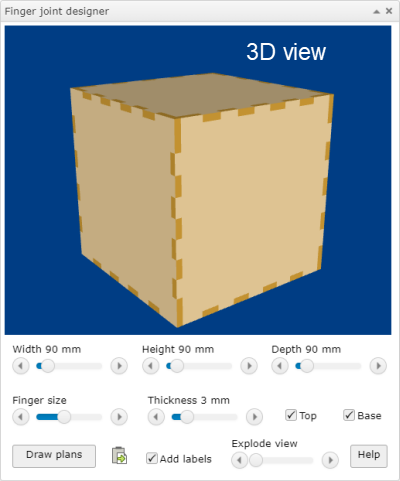
This button on the top toolbar shows a pop-up dialog box where you can design boxes with finger joints on the edges.
The blue area is a 3D view of the box.

Sizes (click here for more information)
Use the width, height and depth sliders to set the dimensions.
Finger size
This slider set the number of fingers on the edges.
Thickness
This slider sets the thickness of the material.
![]() These check-boxes allow you add or remove the lid and add or remove the base of the box.
These check-boxes allow you add or remove the lid and add or remove the base of the box.
Using the 3D view oTo rotate the view, click and drag with the left mouse button oTo zoom the view use the mouse wheel (or pinch on a touch screen) oTo pan the view click and drag with the right mouse button (or drag with 3 fingers on a touch screen)
|
Drawing plans

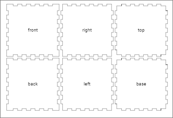
The "Draw plans" button draws each face in the drawing area. The default dimension will just fit on an A4 page. For larger dimensions pat of the drawing will be outside the page area, so you may want to set the page size to A3 .
The plans are drawn as a group with each face labeled unless the "Add labels" check-box is unchecked.
Export to DXF
If you are exporting to DXF remember to remove the text. You can do this by clicking on the text with the ![]() delete tool on the left toolbar. There is no need to change the line width, the export automatically changes the line width to 0.1mm
delete tool on the left toolbar. There is no need to change the line width, the export automatically changes the line width to 0.1mm
![]() Screen capture of the 3D view
Screen capture of the 3D view
This button copies the 3D view to a PNG and adds it to the drawing area. If there is excessive white apace around the image you can use the ![]() crop tool on the left toolbar to remove it.
crop tool on the left toolbar to remove it.
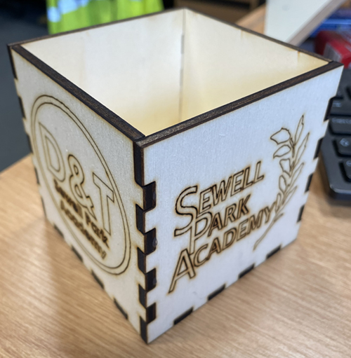
The result of exporting the plans to DXF after of adding some art work to the faces and then laser cutting is shown below.
